
Stickman-Costume
This was made for a halloween-costume. The code runs on an attiny85, mainly to be able to dim the lights down.
Usage
1) Make the costume 2) Solder together the board 3) Upload the code to the atiny 4) Have fun!
Operation
- Hold button
SW2to change brightness/ pwm frequency. - Click button
SW1to go through the modes.
Modes
1) Static This is just a static PWM-signal of the set frequency.
2) Slow Strobe This is a very slow blinking strobe effect.
3) Medium Strobe This is the same strobe effect, just a tad faster.
4) Fast Strobe This is the strobe effect in it's full glory!
Schematic
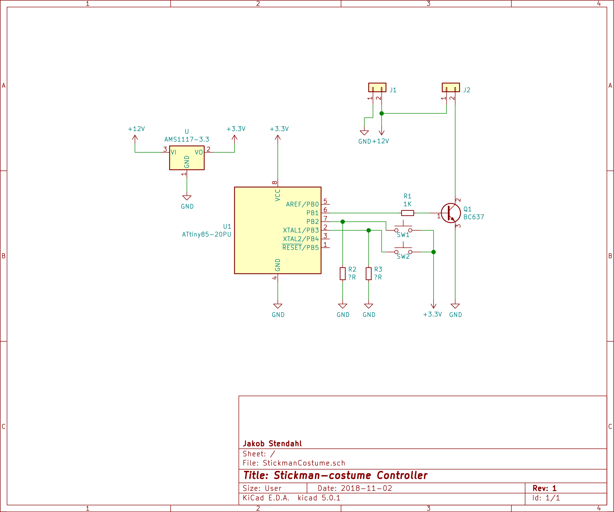
R2 and R3 should be around 10K.
Layout
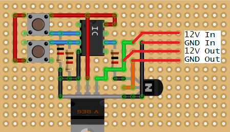
This is the layout i ended up with on my proto-board. The grey wire is the only "jumper" that was put on the top side of the board. All the other wires are "solder-traces" on the bottom side.
I did not use a full-size through-hole voltage-regulator, but a AMS1117-3.3 on the bottom.
Since i didn't have a 8-pin din IC socket i used a 14-pin one, but that does not make a difference either.
The red lines on the far right, is just an explanation of where i soldered my In-Out wires, They are not actually wires, but i soldered wires in where they start. This is the "same" thing as J1 and J2 on the scematic.
Todo
- I have a problem where it looks like it returns to mode
0. I Haven't really figured out if this is due to bad code or bad soldering (or both). But there are a lot of improvements that could be done to the code, reagrding checking button presses. - If you want to do this project, please add a reasonably sized cap (ceramic maybe) near the attiny. I think the problems above are from the chip reseting due to power spikes.