blob: 14f78a0ca08357ec1da4915ff40f24d61bb7ee3e (
plain) (
blame)
1
2
3
4
5
6
7
8
9
10
11
12
13
14
15
16
17
18
19
20
21
22
23
24
25
26
27
28
29
30
|
# Stickman-Costume
This was made for a halloween-costume. The code runs on an attiny85, mainly to be able to dim the lights down.
# Usage
- Upload the code to the attiny
- Solder together the board
- Make the costume
- Have fun!
## Operation
- Hold button `SW2` to change brightness/ pwm frequency.
- Click button `SW1` to go through the modes.
## Modes
1) `Static` This is just a static PWM-signal of the set frequency.
2) `Slow Strobe` This is a very slow blinking strobe effect.
3) `Medium Strobe` This is the same strobe effect, just a tad faster.
4) `Fast Strobe` This is the strobe effect in it's full glory!
# Schematic
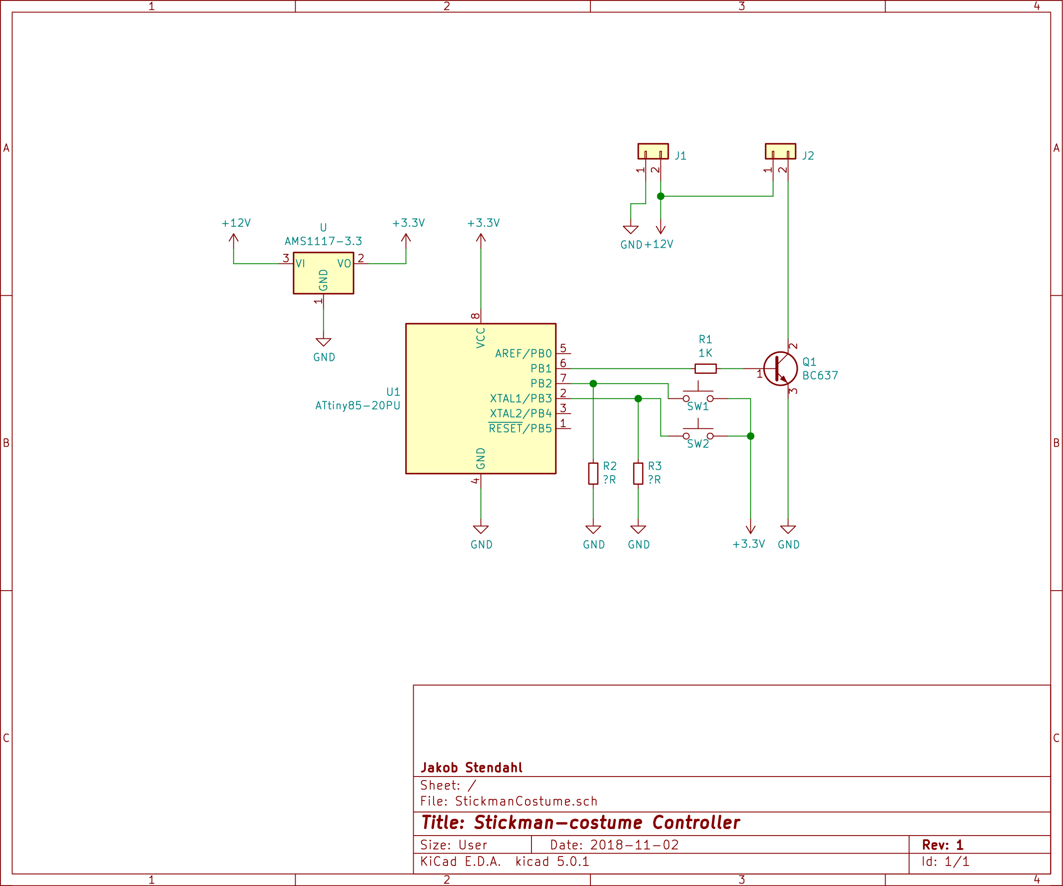
`R2` and `R3` should be around __10K__.
## Layout
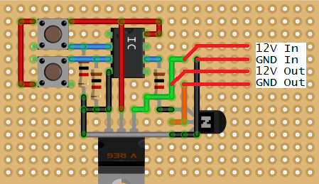
This is the layout i ended up with on my proto-board. The grey wire is the only "jumper" that was put on the top side of the board. All the other wires are "solder-traces" on the bottom side.
I did not use a full-size through-hole voltage-regulator, but a AMS1117-3.3 on the bottom.
Since i didn't have a 8-pin din IC socket i used a 14-pin one, but that does not make a difference either.
The red lines on the far right, is just an explanation of where i soldered my In-Out wires, They are not actually wires, but i soldered wires in where they start. This is the "same" thing as `J1` and `J2` on the scematic.
|
