
diff options
| author | Jakob Stendahl <14180120+JakobST1n@users.noreply.github.com> | 2018-11-03 12:48:09 +0100 |
|---|---|---|
| committer | GitHub <noreply@github.com> | 2018-11-03 12:48:09 +0100 |
| commit | d9bf1ee6bc6036c2485c6b3b1aa4f28311734a7d (patch) | |
| tree | 7f1d4af71afc9bb5a4d0e3efe46785fdf40ca1fd | |
| parent | cef99b257c98c9120e4135695835fe896fd450c4 (diff) | |
| download | Stickman-Costume-d9bf1ee6bc6036c2485c6b3b1aa4f28311734a7d.tar.gz Stickman-Costume-d9bf1ee6bc6036c2485c6b3b1aa4f28311734a7d.zip | |
:memo: Add perfboard-layout and comments
| -rw-r--r-- | README.md | 12 |
1 files changed, 11 insertions, 1 deletions
@@ -17,4 +17,14 @@ This was made for a halloween-costume. The code runs on an attiny85, mainly to b # Schematic 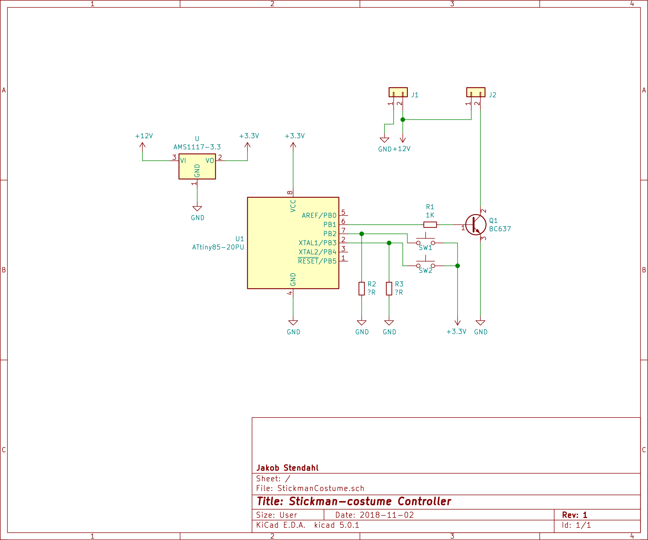 -`R2` and `R3` should be around __1K__. +`R2` and `R3` should be around __10K__. +## Layout +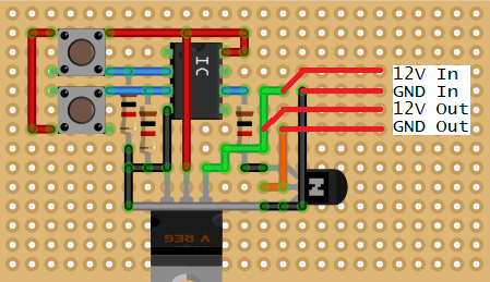 + +This is the layout i ended up with on my proto-board. The grey wire is the only "jumper" that was put on the top side of the board. All the other wires are "solder-traces" on the bottom side. + +I did not use a full-size through-hole voltage-regulator, but a AMS1117-3.3 on the bottom. + +Since i didn't have a 8-pin din IC socket i used a 14-pin one, but that does not make a difference either. + +The red lines on the far right, is just an explanation of where i soldered my In-Out wires, They are not actually wires, but i soldered wires in where they start. This is the "same" thing as `J1` and `J2` on the scematic. |